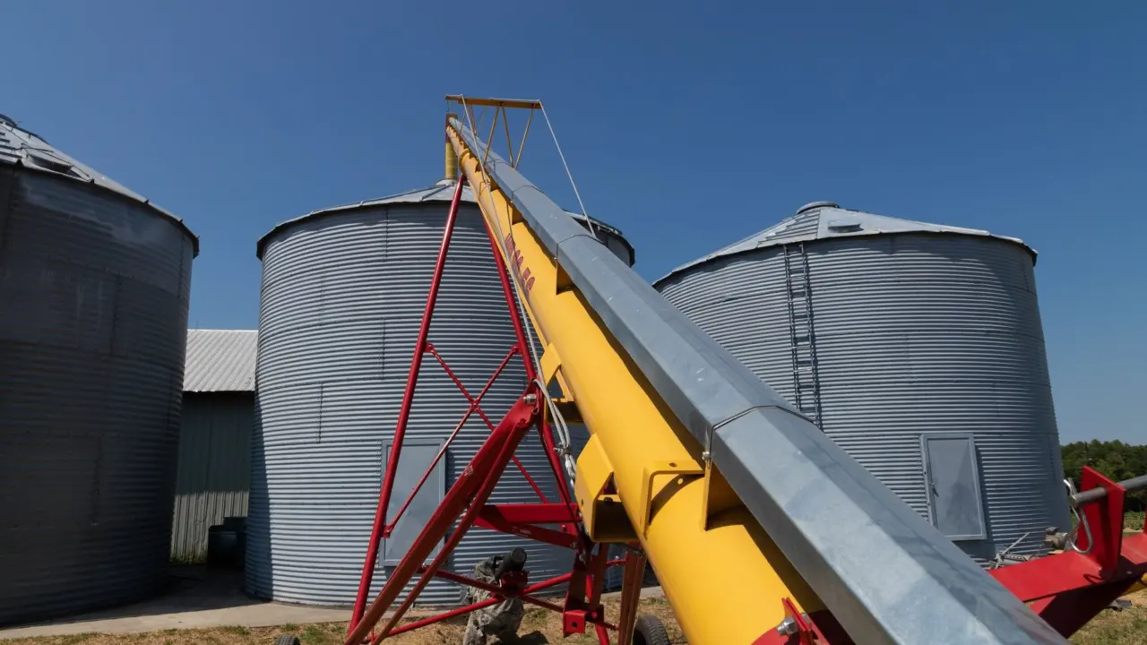
How does a screw conveyor work? A spinning, corkscrew-shaped flight inside a trough pushes material forward by positive displacement and stops it slipping back. A gearmotor turns the shaft, and capacity depends on diameter, pitch, speed and trough loading.
Maybe a feeder keeps starving the process, or a conveyor that worked flat now has to lift material to a new level. Both problems come back to the same few parameters. This guide sits within our wider coverage of powder and bulk solids handling and works from first principles towards sizing decisions.
How the flight moves material along the trough
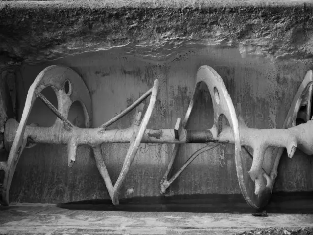
A screw conveyor is a machine that moves material with a spinning, corkscrew-shaped blade inside a tube or trough, as this general reference describes it. The spiral blade is the helical flighting, and it is the part that does the pushing. Material is carried forward along the trough rather than rotating with the shaft.
The positive displacement action is what makes the design dependable. Each turn of the screw pushes material forward and prevents it from slipping back. Nothing relies on air or gravity to move the load, so the conveyor works on dry powders and granules that would be awkward on other equipment.
Feed, discharge and drive position
The inlet of a screw conveyor is always control fed by another device, according to the KWS engineering guide. The conveyor meters and carries material but does not regulate how fast material arrives. If the upstream feed surges, the trough overfills, so it makes sense to control the feed before you tune the screw. Where the feed comes from a storage vessel, the discharge arrangement matters as much as the screw; our notes on silo design for bulk solids cover that side.
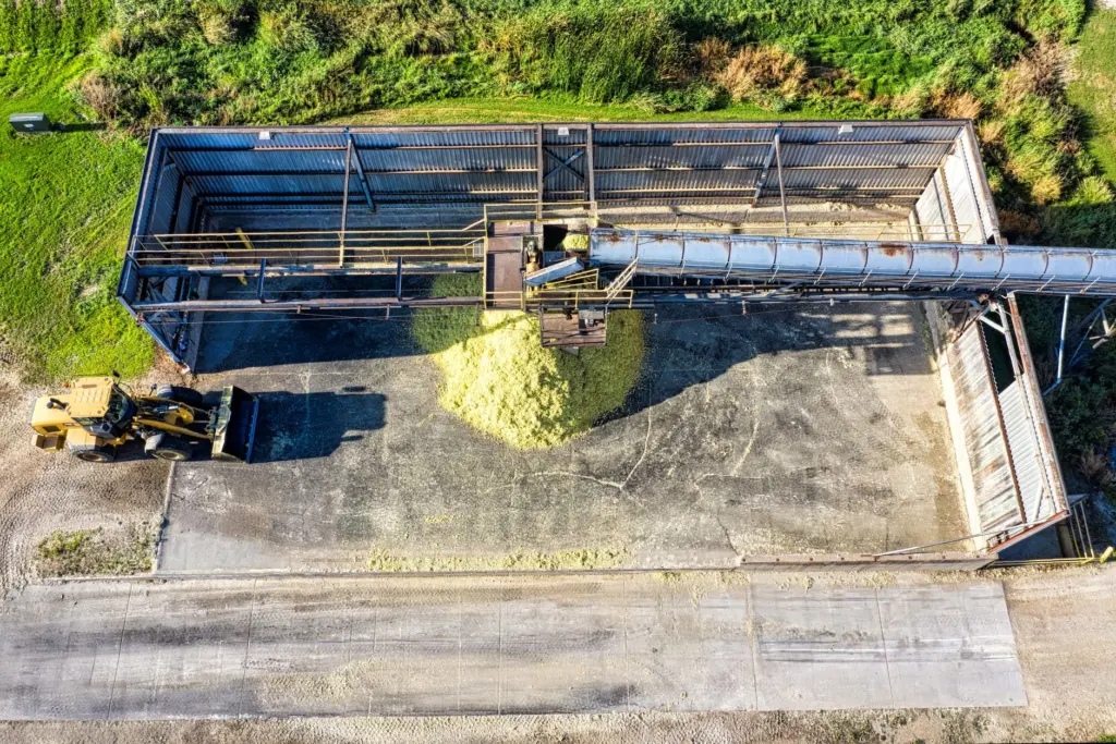
The same guide recommends putting the gearmotor drive at the discharge end. This pulls the material and places the screw sections in tension rather than compression. If you are specifying a new unit, ask for the drive at the discharge end unless layout forces otherwise.
Sizing capacity from diameter, pitch, speed and trough loading
Four things set how much a screw conveyor delivers. Diameter and trough loading decide how much material sits in the trough at any point. Pitch and shaft speed decide how quickly that material is advanced. One vendor guide confirms that flow rate can be controlled by varying screw speed or by adjusting pitch or diameter.
Choosing trough loading by material
The KWS guide notes that screw conveyors are typically designed at 15%, 30% or 45% trough loading. The choice follows the material rather than the target rate:
- 45 percent suits light, free-flowing, non-abrasive materials. Choose this only when the material behaves that way in practice.
- 15 or 30 percent suits denser, sluggish and more abrasive materials. The lower fill leaves room for the material to be carried without packing and wearing the trough.
Treat the loading as a design ceiling for the material class, not a number to push towards. If a material is on the borderline between classes, the lower loading is the safer starting point, and you can raise the diameter or speed instead to reach your rate.
Pitch and speed
Pitch is the spacing of the flight along the shaft. It sits alongside speed in every capacity calculation because both govern how fast the load advances. Faster shaft rotation moves more material, as the general reference puts it, but speed is not free: a higher speed raises wear and drive demand, so size the drive for the duty rather than simply spinning the screw faster.
Pitch needs judgement too. Wetec’s guidance advises adjusting the pitch for efficiency and warns that a tight pitch can cause blockages. If a conveyor chokes on a sluggish material, look at pitch and loading before blaming the feed.
Working through a capacity estimate
Run the calculation in a fixed order so each choice constrains the next:
- Classify the material as light and free-flowing, or dense, sluggish and abrasive, and pick the trough loading that matches.
- Choose a screw diameter. Common diameters are 4, 6, 9, 12, 14 and 16 inches according to Wetec.
- Pick a pitch. Full pitch suits a flat run, while reduced pitch suits a climb.
- Set the shaft speed so that the filled cross-section, advanced by the pitch each turn, delivers the volume per hour you need.
- Convert volume to mass using the bulk density of the material, then check the drive power. The KWS horsepower equation uses a typical drive efficiency of 0.88 for a shaft-mounted reducer and motor.
Final figures should be checked with the manufacturer’s capacity data for the exact screw and material.
When the conveyor has to climb
Inclined screw conveyors typically operate from slightly above horizontal to 45 degrees; steeper units are vertical designs. The cost of climbing is explained in the KWS guide: as incline increases, conveying efficiency falls and horsepower requirements rise. Even the general reference agrees that when the angle gets too steep, the machine cannot move as much material.
| Incline | Typical loss in conveying efficiency | Planning use |
|---|---|---|
| Up to 10 degrees | Minimal | Size close to a horizontal unit |
| Up to 20 degrees | 10 to 40 percent | Allow a margin and consider reduced pitch |
| Up to 30 degrees | 10 to 70 percent | Wide spread, so confirm with the manufacturer for your material |
| Up to 45 degrees | 30 to 90 percent | Compare against a vertical design |
These ranges come from the KWS engineering guide, and the wide spread in the upper rows shows why the figure depends on the material and screw design.
Design choices that help on a slope
Reduced-pitch screws, in the 1/2 and 2/3 sizes, become more efficient than full-pitch screws as the incline increases, per the same KWS guide. Inclines over 10 degrees must also be designed to start and operate under upset conditions, which means restarting with a loaded trough. Do not size an inclined conveyor only for steady running.
A vendor guide from Pneuconveyor goes further and generally limits inclination to 25 degrees or less to prevent material sliding back. Use that as a conservative planning figure for a standard screw, and look at a vertical design when the lift is steep.
Routing around obstacles with a flexible screw
A flexible screw conveyor suits layouts where a rigid straight trough will not fit. The general reference describes centerless augers that are flexible, so they can move feed up, down and around corners. That makes them useful when the conveyor path has to bend between a feed hopper and a distant discharge point.
Treat the flexible design as a routing solution rather than a way round the sizing rules. Diameter, pitch, speed and material behaviour still decide throughput, and a sticky material is as awkward in a bent tube as in a straight trough.
Materials that cause trouble
Screw conveyors are ideal for dry to semi-fluid bulk materials, from free-flowing to sluggish, as the KWS guide states. Materials that are very sticky, or that tend to clump together, may not be suitable, according to Pneuconveyor. Sticky material builds up on the flight and trough, and clumps can pack the space between turns.
If your material sits near that boundary, test a sample with the manufacturer before committing, and consider a lower trough loading and a reduced pitch. When material has to leave a screw conveyor and enter a pneumatic line, plan the transfer carefully, because many of the pneumatic conveying line blockage causes begin with an uneven or overloaded feed.
Frequently asked questions
| Question | Answer |
|---|---|
| How long can a screw conveyor be? | Lengths typically range from a few feet to over 100 feet, according to Wetec. |
| How much can a screw conveyor carry? | Wetec states up to 200 tons per hour depending on design. The KWS guide gives vertical screw conveyors capacities up to 6,000 cubic feet per hour. |
| What powers a screw conveyor? | Drives are typically electric motors, though hydraulic or pneumatic drives are possible, per Wetec. |
| What drive efficiency is used in horsepower calculations? | KWS uses a typical value of 0.88 for a shaft-mounted reducer and motor. |