| Aspect | Typical value or condition | Planning use |
|---|---|---|
| Vane count | Typically 6, 8, or 10 vanes per rotor | Vane count affects how effective the airlock is, so compare it when leakage matters. |
| Staggered pocket rotor | 16 offset pockets | Consider it when a smoother, continuous feed matters more than a simple rotor. |
| Tip clearance, high-pressure duty | Often less than 0.0079 in (0.2 mm) | Treat it as a ceiling for tight-sealing duty and confirm the working figure with the valve manufacturer. |
| Pressure differential | Often up to 15 or even 22 PSIG in high-pressure applications | This is the condition under which tight clearance and heavy construction pay off. |
| High-heat duty | Rotor and housing metal expands in applications up to 750°F | Raise thermal expansion with the supplier before fixing the clearance. |
Figures from Prater Industries’ rotary valve guide and, for the staggered rotor, ACS Valves’ rotor guide.
How does a rotary valve work? A pocketed rotor turns inside a close-fitting housing, carrying material from inlet to outlet while a very small gap limits air passing back. Match rotor, clearance and sealing to the material.
This guide follows the valve from operation through selection, setup and upkeep. It belongs to the wider topic of powder and bulk solids handling, but it stays on the valve itself rather than the conveying system around it.
Operating cycle inside the housing
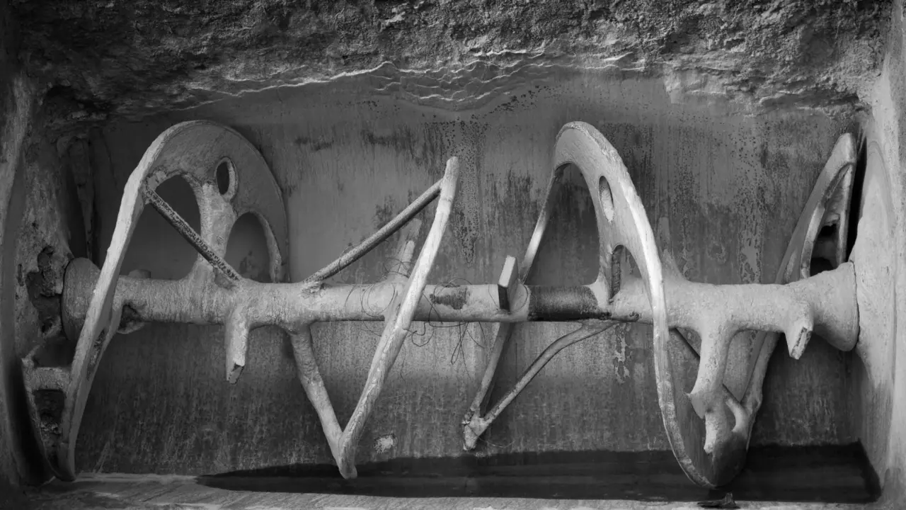
A rotary airlock valve has two main functions, according to AirlockFeeder’s explanation of the rotary valve. It regulates bulk material flow through the system and it prevents air leakage. The rotor does the metering and the housing forms the seal around it.
One turn of the rotor repeats the same cycle:
- Fill the pockets. Material arriving at the inlet packs into the spaces between the rotor blades.
- Carry the charge. The pockets move the material across the housing surface towards the outlet.
- Discharge. As the rotor continues to turn, the material is discharged to the lower part of the valve, as Verspec’s working-principle description puts it.
- Return empty. The pockets travel back towards the inlet. By design they carry some air with them, as the Prater guide notes.
The seal is the very small gap between rotor and housing. Verspec says this gap effectively prevents the reverse flow of airflow, which is why that clearance is the figure to watch later. AirlockFeeder also describes the valve’s rotation as either load side or return side.
Selection: valve body and entry style
Choose the body style first, because it decides how air and material meet the rotor. The Prater guide separates the main options.
Drop-through valves
A drop-through valve has a high-capacity, simple design. It suits general dust collection and gravity-fed duty, where material falls through the valve without a conveying air stream passing through it.
Blow-through valves
In a blow-through valve, the conveying air line is plumbed directly through the bottom of the valve housing. The valve then feeds material into a moving air stream. This is the arrangement behind most rotary valve for pneumatic conveying duty.
Side entry and heavy-duty builds
Fragile material needs a different entry. A standard top-entry valve can act like a pair of scissors on the product, and a side-entry design minimizes that shearing. For tough duty, heavy-duty units add thicker castings, oversized shafts and outboard bearings. Abrasive material can destroy a standard cast iron valve in weeks, so abrasive duty justifies the heavier construction.

Selection: rotor types
Rotor choice follows the material: how abrasive, how sticky, how fragile and how smooth the feed must be. The vane count also matters. Prater Industries says rotors typically have 6, 8, or 10 vanes and that this number determines the effectiveness of the airlock.
| Rotor type | Design feature | Where it suits |
|---|---|---|
| Open end | Blades reach the endplates | Duties where cleaning and maintenance access matter, as it is generally easier to clean and maintain than closed end. |
| Closed end | A disc on the blades keeps them from touching the endplates | Extremely abrasive material, and flake or chip material. |
| Staggered pocket | 16 offset pockets | Continuous, smooth movement of material into the system. |
| Reduced volume | Lower cubic feet per revolution (CFR) inside the valve | Controlling flow where a standard pocket volume passes too much. |
| Helical | Angled blades | Cutting action if material gets caught between rotor and housing. |
| Adjustable tip | Tips slide outward as they wear | Keeping clearance near its starting point on wearing duty. |
| Radius pocket | U-shaped pockets | Sanitary or food-grade valves, because the shape minimizes packing in the crease of a vane. |
Rotor types as described by ACS Valves.
In practice, pick open end as the default when cleaning access is the priority. Move to closed end when abrasion or flake material is the problem. Pocket volume is quoted in cubic feet per revolution, so a reduced-volume rotor is the tool when the standard pockets deliver more than the process needs.
Setup: tip clearance and air leakage
How much clearance should a rotary valve have?
There is no single figure for every valve. Prater Industries gives tip clearance often less than 0.0079 in (0.2 mm) for high-pressure applications. Lower-pressure duty can sit looser, and the exact figure for your valve comes from the manufacturer’s manual. Heat changes the answer: in applications up to 750°F, the metal in the rotor and housing expands, so a clearance set cold may not hold in service.
What drives air leakage
- Displacement air. Pockets carry some air back to the inlet by design, so some air movement is normal even in a healthy valve.
- Gap size. The small gap between vane and housing stops reverse airflow, as Verspec explains. As the gap grows, air leakage rises sharply, according to Prater.
- Pressure. Applications often run up to 15 or even 22 PSIG, which is where a worn or loose gap costs the most.
- Shaft seal. Seal purge kits introduce a small amount of pressurized air into the packing gland area around the shaft seal. Ask whether the supplier offers them for your duty.
Wear is the quiet cause of leakage, because the gap opens gradually. Adjustable rotor tips let you slide the tips outward as they wear, which keeps the clearance close to the starting point.
Running in pneumatic conveying
A rotary valve under a silo or cyclone can feed a conveying line, but this duty exposes the valve’s weak points. Misapplication shows up quickly in the following problems.
- Inconsistent pocket filling. Air blowing back through the valve causes turbulence that can keep light or low bulk density materials from entering the pockets consistently. Discuss light powders with the manufacturer before choosing the rotor and clearance.
- Leakage that grows with wear. As the vane-to-housing gap increases, leakage rises sharply, so a valve that once sealed well can start to upset the line. Measure the gap on a schedule and use adjustable tips where the duty allows.
- Product shearing. Fragile material suffers in a top-entry valve, so use a side-entry valve for it.
- Fast wear on abrasive material. Abrasive material can destroy a standard cast iron valve in weeks. Closed-end rotors and heavy-duty construction are the answer, rather than more frequent replacement of a light valve.
These points come from Prater’s guide and ACS Valves. Matching the valve to the duty up front costs less than correcting these faults later.
Upkeep: how to maintain a rotary valve
Maintenance centres on the gap, the shaft seal and access to the rotor. Manuals set the intervals for each model, so follow yours. Duty changes the cadence: abrasive material wears a valve in weeks, so inspect it more often than a valve handling benign material.
- Isolate the valve. Follow the site procedure before opening any part of the housing.
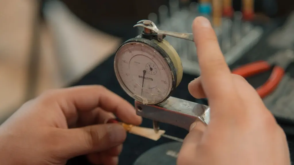
- Check the gap. Measure rotor-tip clearance against the manufacturer’s figure, because leakage rises as the gap increases.
- Reset adjustable tips. Where fitted, slide the tips outward to restore clearance as they wear.
- Inspect the shaft seal. Look at the packing gland area and, if a seal purge kit is fitted, confirm it is supplying its small flow of pressurized air.
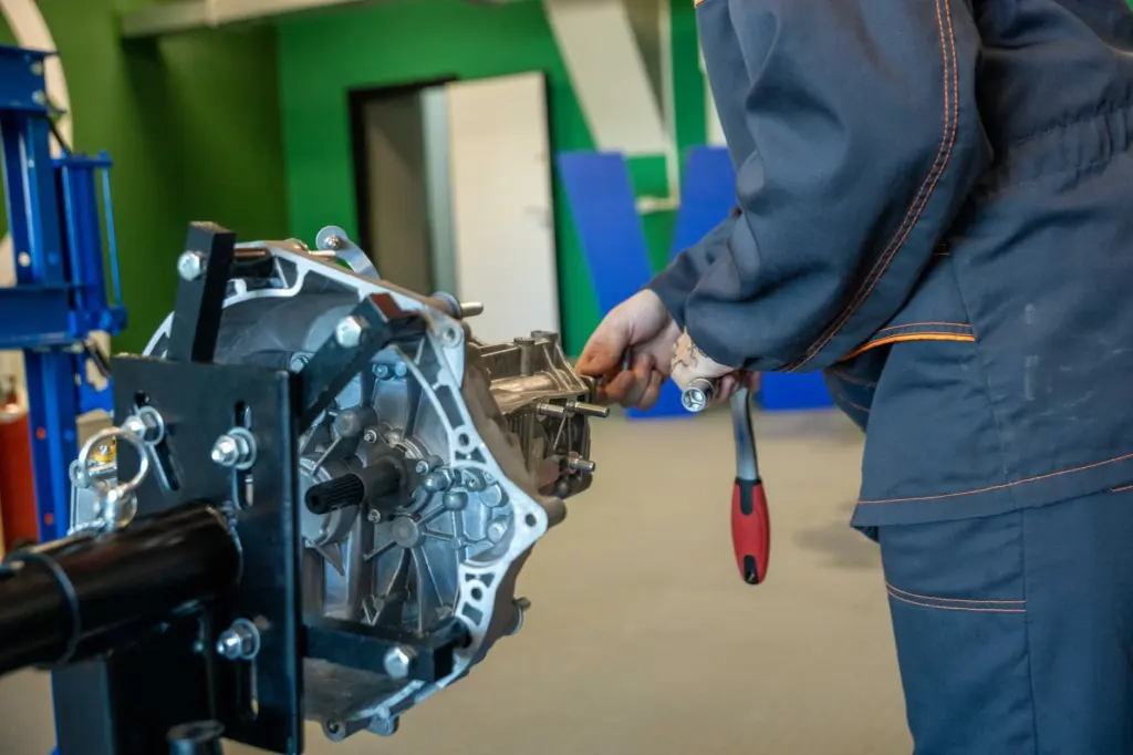
- Pull and clean the rotor. Quick take-apart designs let the rotor slide out on precision rails without tools. Open-end rotors are generally easier to clean than closed-end ones.
Heavy-duty valves add outboard bearings and oversized shafts, which suit tough duty. They do not remove the need to check the gap. AirlockFeeder warns that an incorrectly used valve can lead to inadequate efficiency, equipment wear and accelerated product degradation, so upkeep alone does not fix a valve that is wrong for the material.
Beyond the valve
A rotary valve rarely works alone. For the equipment that often meters material downstream, read how does a loss in weight feeder work. For weighing and batching layouts, see powder batching system design.
Frequently asked questions
Where are rotary valves typically used?
Typical applications include discharging silos, discharging cyclones, dust collection systems and pneumatic conveying.
What are load side and return side rotation?
They are the two rotation types described for rotary valves. Confirm with the manufacturer which applies to your valve and installation.
What happens if a rotary valve is used incorrectly?
An incorrectly used valve can lead to inadequate efficiency, equipment wear, accelerated product degradation and production loss, according to AirlockFeeder.