Quick answer: Good dust collection hood design means enclosing the emission wherever you can, placing the hood as close to the source as the process allows, and giving every capture point its own required airflow. Open canopies are the costly last resort.
The hood is the first of the three stages in industrial dust collection systems. This guide stays on that capture side: choosing and placing hoods at transfer chutes, bag unloaders and manual stations, not sizing the collector or routing the ductwork.
Choosing a hood type
Dust collection is three systems in series: capture at the source, transport through ductwork, and separation in the collector, as the dust collection selection and design guide puts it. A weak hood cannot be rescued downstream, so the choice of hood type sets the airflow the rest of the system must supply.

Four criteria decide the choice:

- Can the source be surrounded? If the emission point can be enclosed, an enclosing hood almost always wins on airflow demand.
- Is the process throwing dust in a known direction? If it is, a receiving hood placed to catch that stream can work where full enclosure would block the operation.
- How close can the opening sit? Distance from the source has a very large effect on airflow, covered below.
- What does the budget allow? External hood types trade performance against cost.
| Hood option | Performance and cost position | Planning use |
|---|---|---|
| Enclosing hood | Surrounds the emission and needs a fraction of the airflow of an open canopy | First choice at transfer points, bag dumps and other fixed sources |
| Receiving hood | Sits where the process delivers the dust | Use where the operation cannot be enclosed but the dust path is predictable |
| Flanged external hood | Raw edge with an added flange, about 30% better performance than a raw edge | A cheap upgrade for manual stations and slot-style openings |
| Bell mouth external hood | Best performance and highest cost of the five external hood types | Worth the cost where airflow efficiency matters most |
Performance rankings come from Bobo Machine’s dust collection design article, which lists five external hood types running from raw edge to bell mouth, and the enclosure comparison from the selection and design guide.
Enclosing hood vs receiving hood
An enclosing hood surrounds the emission, while a receiving hood is positioned to catch dust that the process already sends in a particular direction, such as the stream thrown off a grinding wheel. The practical difference is airflow. A hood that surrounds the emission needs a fraction of the airflow of an open canopy, so enclosure cuts the volume your collector has to move.
Choose an enclosing hood when the source is fixed and access can be managed with doors, curtains or small openings. Choose a receiving hood when the operator needs open access and the dust path is consistent. A receiving hood that is too far from the stream behaves like an open canopy and loses the benefit, so treat placement as part of the selection, not a later adjustment.
Placing the hood and setting airflow
Hood position relative to the source strongly changes required airflow. In one published example, moving a 4-inch hood from 12 inches to 6 inches away from the dust source cut the required airflow from 1,009 CFM to 259 CFM. Before specifying a bigger collector, check whether the hood can be moved closer or enclosed further.
Capture velocity
Capture velocity is the air speed needed at the point of dust release to pull the dust into the hood. The classic engineering reference for hood design and capture velocities is the ACGIH Industrial Ventilation manual, which tabulates ranges by how the dust is released. Take your design value from that manual for your own dispersion condition rather than from a rule of thumb. The same guide notes that each capture point has a required airflow, so every hood on a system needs its own figure.
Typical airflow reference points
| Capture point | Typical duct size | Typical airflow | Planning use |
|---|---|---|---|
| Conveyor transfer point | 6-10 in | 500-1,500 CFM | Starting range for enclosed transfer points before detailed design |
| Grinding station | 6-8 in | 1,000-2,000 CFM | Higher demand where dust is thrown off at speed |
| 4-inch hood at 12 in from source | 4 in hood | 1,009 CFM | Shows the penalty of a distant opening |
| 4-inch hood at 6 in from source | 4 in hood | 259 CFM | Shows the saving from moving closer |
These figures are typical values quoted in Bobo Machine’s design article. Use them to sense-check a design, not as a substitute for a calculation at your own source.
Manual powder stations
At a bench-top station the operator’s hands and body limit how close or enclosed the hood can be. A flange on the hood opening is the simplest improvement, because a flanged hood performs about 30% better than the same hood with a raw edge. Keep the slot or opening as near the work as the task permits.
Conveyor transfer points
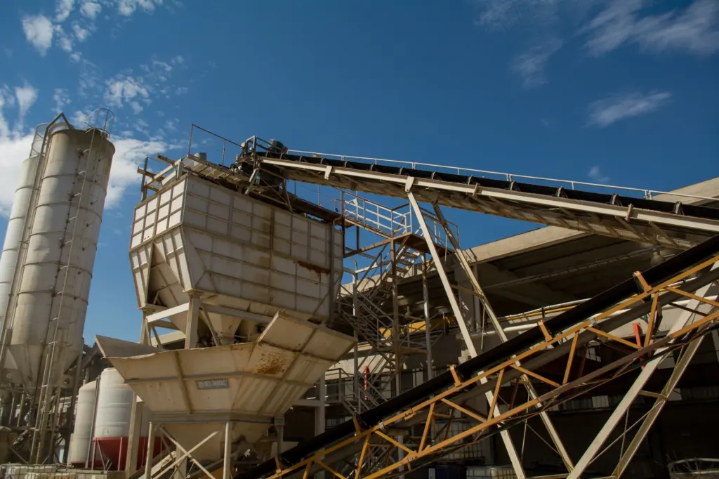
Material transfer points such as conveyors, chutes and hoppers are a primary dust source, and each one is a capture point with a required airflow. The reliable approach is to enclose the transfer and extract from the enclosure, so that the hood is doing the job of an enclosing hood rather than fighting open air.
For conveyor transfer point dust control, work through this order:
- Enclose the transfer as completely as the equipment and maintenance access allow.
- Connect a take-off duct from the enclosure and size the airflow for that specific point, starting from the typical range of 500-1,500 CFM for a 6-10 in duct.
- Fit a blast gate at the branch connection so idle equipment can be isolated and airflow concentrated where material is moving.
- Confirm the airflow actually reaching the pickup point once the ductwork is built.
Enclosure is the stronger route because it lowers the airflow demand, so the same collector can serve more points. Dust capture at transfer points that relies on a loosely placed open hood tends to need the most airflow for the least result.
Bulk bag unloaders
A bag dump or bulk bag unloader is a capture point with a required airflow, just like a transfer chute. Bulk bag unloader dust containment should therefore be designed as enclosed capture around the discharge, with an extraction connection sized for that point, not added as an afterthought to the bag frame.
Treat the opening where the bag connects, the hopper below it and any spout as parts of one enclosure. The less open area the extraction has to draw across, the less airflow it needs. Storage vessels filled downstream have a different problem, because displaced air is handled by a bin vent filter rather than by a capture hood.
Troubleshooting weak capture
- Dust escapes despite adequate collector size. Static pressure from ductwork reduces delivered airflow, so longer runs and elbows reduce what arrives at the pickup point. Measure the airflow at the hood, not at the collector.
- The hood works until other branches open. Idle branches steal airflow. Close them with blast gates at each branch connection.
- The opening is far from the source. Move it closer or enclose further before increasing fan capacity.
- Performance fades over time. Include the hoods and take-offs in the routine described in the dust collector maintenance checklist.
Frequently asked questions
How much safety margin should the airflow include?
Adding a 10-20% safety margin to peak airflow requirements accounts for system losses, according to Bobo Machine’s design article.
Which standard covers combustible dust on the collector side?
The NFPA 652 framework ties dust testing, hazard analysis, venting and isolation together, as summarised in the dust collection selection and design guide. Confirm what applies to your dust before finalising any hood design.
Can modelling help with a difficult hood?
Yes. In a paper mill roller case study, Synergetics used CFD modelling to assess dozens of hood designs. The finished hood captured 95% of the dust generated, with an 89% reduction in settled dust and 90% less energy use.
Is a larger collector a fix for a poorly placed hood?
No. Capture, transport and separation are separate stages, and a hood that fails at the source passes its problem on to the next. Fix the capture point first.