Velocity targets at a glance
| Dust or condition | Vendor-recommended velocity | Planning use |
|---|---|---|
| Fine dust | 3500–4500 ft/min | Choose a design velocity inside this band for light powders that stay airborne and need steady transport. |
| Medium dust | 3000–4000 ft/min | Use as the default window when the material is neither very fine nor fast-settling. |
| Coarse dust | 2500–3500 ft/min | Allows a lower target, but check settling risk before choosing the bottom of the range. |
| Optimal band overall | 3000–4500 ft/min | Efficient transport and even distribution; aim inside it unless the dust demands otherwise. |
| Too low | Below 3000 ft/min | Settling and insufficient transport; treat as a warning floor. |
| Too high | Above 4500 ft/min | Wear, re-entrainment and turbulence; treat as a ceiling, not a target. |
These bands come from a collector manufacturer’s inlet design guidance, which ties velocity to dust fineness and to the point where settling or wear begins.
Good dust collection duct design starts with a velocity high enough to keep dust moving and low enough to limit wear, then sizes every run around it. Work from hood to collector in the order below.
The ductwork is the part of industrial dust collection systems that links each capture point to the collector, so a mistake here shows up as dust on the floor or a fan that cannot deliver. The vendor figures above describe collector inlet velocity. Use them as a starting window, then confirm the final duct velocity against the ventilation guidance that governs the project and the behaviour of the dust itself.
Stage one: define the capture requirement at each hood
Every duct run is sized to carry the airflow its hood needs, so the hood comes first. Decide what airflow each capture point must draw before choosing any pipe diameter, because the airflow and the velocity together fix the duct size.
- List the capture points. Record each hood, its location and the dust it will handle, noting whether the powder is fine, medium or coarse.
- Set the airflow per hood. Take the figure from your hood design basis and keep it as a fixed input for the later steps.
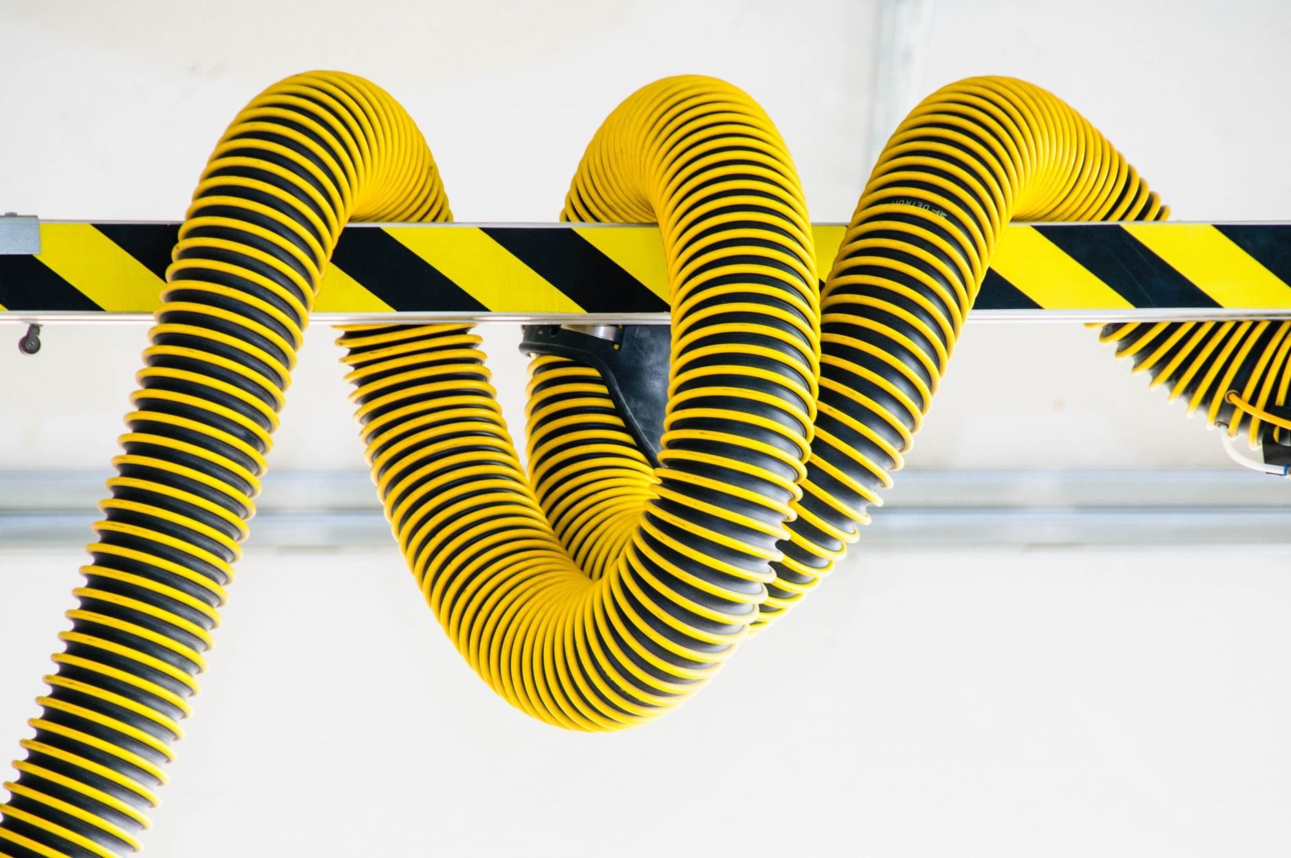
- Note the connection type. A flexible hose at the hood is convenient for movable capture points, but the bends and corrugations in it behave like the abrupt changes described later.
The hood itself is a transition from open room air into a confined duct. A manufacturer’s guidance says abrupt changes in direction create turbulence and raise pressure drop, and smooth transitions reduce both. The same logic favours a tapered hood-to-duct transition over a sudden step, and it gives a practical reason to keep flexible hose as short and straight as the layout allows.
Stage two: choose the conveying velocity
The velocity that keeps dust from settling depends mainly on how fine and how heavy the dust is. In the manufacturer’s guidance, fine dust is paired with 3500–4500 ft/min, medium dust with 3000–4000 ft/min and coarse dust with 2500–3500 ft/min, and anything under 3000 ft/min is flagged for settling and insufficient transport.
Turn that into a decision with three rules.
- Fine, light powders: choose a target in the upper half of the optimal band, because these materials are the least tolerant of a velocity that drifts low in a long run.
- Coarse or fast-settling material: a lower band is listed, but the settling warning applies below 3000 ft/min, so keep the design margin on the safe side of that line rather than aiming at the bottom of the coarse range.
- Abrasive material: do not push toward the top of the band. The same guidance associates velocity above 4500 ft/min with increased wear, re-entrainment and turbulence, so that figure is a ceiling.
A branch carrying only a little airflow is the usual place where velocity falls out of the window, since the airflow per hood is smaller than on the main. Check every branch on its own rather than assuming the main’s velocity applies.
Stage three: size the diameter from airflow and velocity
Duct diameter follows directly from two inputs: the airflow the hood needs and the velocity you selected. The required cross-sectional area equals airflow divided by velocity, and the round diameter is whatever gives that area.
- Take the hood airflow from the previous stage and the design velocity from the optimal band.
- Divide airflow by velocity to get the area, then convert the area to the nearest practical standard diameter.
- Recalculate the real velocity with the standard diameter. Rounding up lowers it, rounding down raises it.
- Test the result against the band. If a rounded-up duct drops below 3000 ft/min, step down a size; if a rounded-down duct exceeds 4500 ft/min, step up. Both limits are from the manufacturer’s velocity guidance.
- Repeat for each branch, then size the main for the combined airflow of the branches it serves, again checking the velocity.
Round duct is the usual choice for dust service because the velocity is even around the section. Rectangular duct is easier to fit in some building spaces, but corners are where material can collect, so confirm the velocity at the smaller dimension before accepting it.
Stage four: account for pressure loss in fittings, branches and hoods
Static pressure loss is the resistance the fan must overcome, and elbows, branch entries and hoods each add to it on top of straight-run friction. The manufacturer’s guidance states that sharp angles or abrupt changes in direction create turbulence and increase pressure drop, while smooth transitions minimise both.
Elbows and fittings
Every elbow is a change in direction, so gentler bends cost less than tight ones. Prefer long, sweeping bends where space permits, and reserve tight elbows for places with no alternative. High velocity also wears elbows fastest, which is another reason to stay at or below the top of the optimal band.
Branch entry
A branch joining the main is a change in direction for the entering air. Join branches at a gradual angle rather than square to the main, and merge them in the direction of flow, so the turbulence that raises pressure drop is kept to a minimum. Branches that enter close together or opposite each other make the flow less even, so space them along the main.

Hoods
The hood entry is usually the largest single loss on a branch because the air accelerates from still room air into the duct. A tapered transition from hood face to duct reduces that loss compared with an abrupt step, in line with the smooth-transition principle above.
Totalling the system
Add the losses along each path from hood to collector: hood entry, straight run, elbows, branch entries and the collector inlet. The path with the highest total sets the fan requirement, and the other branches are balanced against it, typically with dampers. Re-check velocity after balancing, since closing a damper on a branch lowers its airflow and can push it below the settling floor.
Stage five: connect the duct to the collector inlet
The duct ends at the collector inlet, and inlet design affects both distribution and wear. High inlets are typically preferred for heavier dusts or applications where dust settles quickly, according to the same inlet design guidance, which also lists smooth transitions as a way to limit turbulence and pressure drop.

Ductwork sizing and filter sizing are separate decisions that meet at the collector: the filter side is covered in the guide to air to cloth ratio, and media cleaning is covered in the guide to dust collector pulse cleaning. Finalise the duct network once those collector choices are fixed, so the airflow total matches the unit you are connecting to.
Troubleshooting duct performance
- Dust settling in horizontal runs: measured velocity is likely below the optimal band. The guidance links velocity under 3000 ft/min to settling issues. Check for oversize duct, closed dampers or a branch carrying less airflow than designed.
- Worn elbows or dust carrying back into the airstream: velocity above 4500 ft/min is associated with wear, re-entrainment and turbulence. Reduce the velocity by moving to a larger diameter, or check whether a damper adjustment pushed too much air down one branch.
- Weak capture at a far hood despite correct sizing: look for sharp bends, abrupt transitions or tight branch joins on that path, since each adds turbulence and pressure drop.
- Imbalance after adding a branch: a new hood changes the pressure loss on every path. Re-total the paths and re-verify branch velocities.
Frequently asked questions
Does the right duct velocity depend on the type of dust?
Yes. The manufacturer’s guidance gives a lower window for coarse dust and a higher one for fine dust, with an overall optimal band of 3000–4500 ft/min, as set out in its inlet design table.
Why do sharp bends matter for a dust collection system?
They create turbulence, which increases pressure drop, so the fan has more resistance to overcome. Smooth transitions reduce that effect.
When is a high collector inlet the better choice?
It is typically preferred for heavier dusts or for dust that tends to settle quickly.
Can the same velocity be used for every branch?
Not automatically. Each branch has its own airflow and diameter, so verify each one against the velocity window rather than copying the main’s value.