Dust collector differential pressure is the pressure difference across the filter media, read in inches of water gauge (in. w.g.). Typical readings run from 1 to 2 in. w.g. with new filters to 4 to 6 in. w.g. with dust-loaded ones.
The reading works as a measurement of filter condition, so what matters is where it is taken, how it is read and how it moves over time. For the wider equipment context, see industrial dust collection systems. For diagnosing specific faults, see dust collector troubleshooting.
What differential pressure measures
Differential pressure (dP) is the difference between pressure measurements at two points in a system, according to a baghouse manufacturer’s explanation. In a dust collector, one point sits on the dirty side of the filters and the other on the clean side. The gauge shows only the gap between them, not the absolute pressure at either point.
That gap exists because the filter media resists airflow. As dust builds up on and in the media, the resistance rises and the reading climbs. This is why dP serves as a proxy for how loaded the filters are, and why it is expressed in inches of water gauge (in. w.g.), a unit also written as inches of water column. Every figure in this guide is in that unit.
Because the reading is a difference, it says nothing about airflow or dust concentration on its own. It reports the combined resistance of everything between the two tap points, which in a baghouse is mainly the filter media and the dust cake on it.
Where the pressure taps sit
A pressure tap is the connection point that feeds each side of the gauge. One tap goes into the dirty plenum and the other into the clean air plenum. Placement affects whether the reading is trustworthy.
A collector-parts supplier’s installation guidance gives these placement rules:
- Plenum corners: air taps are best placed near the corners of the clean and dirty plenums.
- Wall clearance: keep taps at least 6 in. from the walls where practical, and in the corners.
- Line length: avoid air line runs over 100 ft, because long runs may affect the accuracy of the readings.
For a gauge mounted on the housing, the runs are short and the limit is rarely a concern. It matters more when the gauge or transmitter is mounted in a remote control room. In that case, move the instrument closer rather than accept a long run.
Reading a Magnehelic gauge
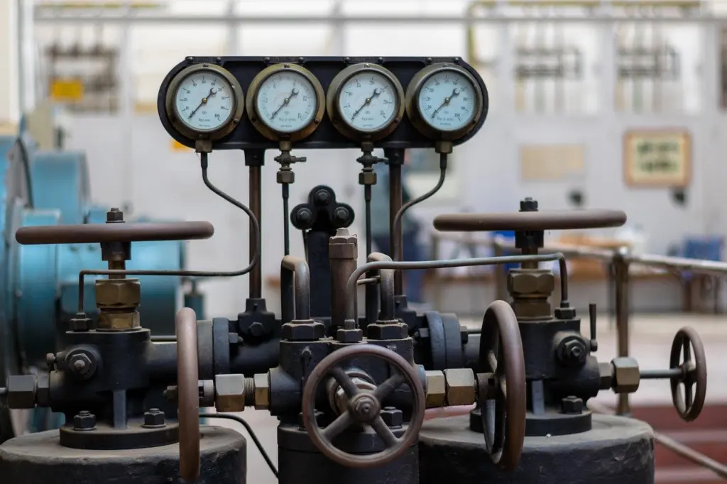
A Magnehelic-style gauge is a simple dial instrument that shows dP directly. Per the baghouse manufacturer, the gauge may be analog or digital, with readings from zero to 10 in. w.g. Since normal operating values sit well inside that span, a gauge of this range suits a typical baghouse.
Zeroing and connecting
Zero the gauge before installing both lines, as the installation guidance instructs. A gauge that does not rest at zero with no pressure applied will add that offset to every later reading and quietly distort any trend.
Interpreting the needle
Read the needle against the printed scale in in. w.g. A reading that sits near the low end of the scale is the expected picture for clean filters. As the needle climbs, the filters are loading. If the needle falls below zero, the lines are probably mixed up, and the same guidance advises switching the lines on the inputs. A negative reading is therefore a wiring symptom first, not a process finding.
Normal, rising and falling readings
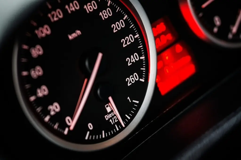
No single number is correct for every collector, but the manufacturer’s ranges give a useful frame. The same source states that readings above 6 in. w.g. indicate that the filter’s life cycle is at its end.
| Condition | Typical dP | Planning use |
|---|---|---|
| Newly installed filters | 1 to 2 in. w.g. | Expected starting point after a filter change; a reading far outside it suggests a gauge or installation check. |
| Older filters loaded with dust | 4 to 6 in. w.g. | Normal for aged filters; time to plan replacement as the needle approaches the top of the range. |
| Above the loaded range | Above 6 in. w.g. | Indicates the filter life cycle is at its end; replace the filters. |
The ranges above come from the baghouse manufacturer’s differential pressure explanation.
Rising readings
A slow upward drift as filters age is the expected pattern. It becomes a decision point when the reading moves from the new-filter range toward and beyond the loaded range. Read it as a schedule signal: it tells maintenance when filters are approaching replacement, and the dust collector maintenance checklist is the place to tie that to routine inspection.
Sudden changes in either direction
A sudden change is a different signal from gradual loading. The baghouse manufacturer notes that when significant changes occur in pressure, some type of issue exists. The reading does not say which issue, so treat an abrupt jump or drop as a reason to inspect the system, not to wait for the filters to age. A falling reading is not automatically good news, since a drop that does not follow a filter change or cleaning cycle also counts as a significant change. Fault-finding steps are covered in the troubleshooting guide linked above.
Differential pressure and on-demand cleaning
On-demand cleaning uses dP as its trigger. A pressure transmitter sends a signal, and when it reaches a set value, a control system triggers the cleaning system. The manufacturer’s description adds that the system pulses until the pressure lowers to the set point across the baghouse.
This makes the set points part of the measurement setup. A cleaning start value and a stop value define the band the collector operates in, and a gauge reading well outside that band is a prompt to check whether cleaning is running as designed.
Logging trends and managing energy cost
A single reading shows the present state. A log of readings shows direction and speed, which is what supports decisions. Record dP at regular intervals, note when filters are changed, and compare each new value with the earlier ones. A steady climb between changes is routine, while a step in the log stands out in a way a glance at the dial does not.
The baghouse manufacturer ties this kind of monitoring to a system that performs with lower maintenance and operational costs. Pressure drop matters for energy use because a collector running with filters near the end of their life, or with cleaning out of band, is operating against more resistance than a well-maintained one. The source supports the cost link in general terms. It gives no figure, so energy savings are best judged against the collector’s own log.
Frequently asked questions
Can a Magnehelic gauge control the cleaning system?
No. The installation guidance describes these gauges as simple and reliable, but they cannot alone control a baghouse cleaning system. Automated cleaning needs a transmitter or controller.
What does a differential pressure switch do?
An electro-mechanical switch monitors pressure and trips when it rises or falls beyond a preset value, according to the baghouse manufacturer. It acts as an alarm, so it flags an out-of-range condition without showing the actual value.
Why set a baseline profile after replacing filters?
The same manufacturer advises establishing a baseline differential profile for the system once the filter has been replaced. Later readings can then be judged against how that collector actually behaves, not only against general ranges.